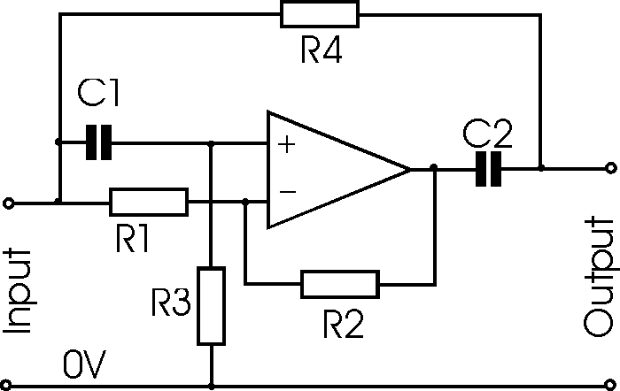
Notch Filter Circuit Diagram Draussen Ich Habe Mich Fertig G
Filter notch twin circuit active high hz 60hz audio 60 schematic network simulation op amp filters frequency am circuits amplifier Notch filter op amp circuit Notch filter adaptive ccrma
Notch Filter Circuit Design - Circuit Diagram
Notch filter circuit diagram mc33171 under audio filters circuits Filter notch circuit twin basic band stop filters below theory application reject electrical parallel shown figure Notch filter (bandstop): what is it? (circuit & design)
Passive notch filter circuit diagram
Notch filter circuits fliege circuit homemade designing tuning twin advantages incorporates precision couple just details fulfill cs components rs formNotch filter circuit band stop electrical4u characteristics transfer function rlc Variable notch filter circuitNotch filter design: a narrow band filter for specific noise attenuation.
Notch filter is insensitive to component tolerancesWhat is notch filter? Notch filter circuit designFilter notch circuit passive band stop bandstop electrical4u transfer function.

60 hz notch filter circuit
Solved in the notch filter circuit shown in the figure,Notch filter circuit twin circuits schematic designing homemade Notch filter circuits with design details – homemade circuit projects60hz notch filter.
Simple variable notch filter circuitNotch filter circuit active stop band electrical4u transfer function Notch filter 60hz circuit twin analogCircuit filter notch seekic.

Notch variable
Op ampFilter notch circuit adjustable diagram simple schematics electronic Simple notch filter uses an operational amplifierT resistor network calculator.
Notch filter (bandstop): what is it? (circuit & design)Notch filter circuits with design details – homemade circuit projects Simple adjustable notch filter circuit diagramNotch filter circuit as an example..

Notch example
Notch filter: how to make a notch filterNotch filter: the circuit’s diagram and the design formula – electronic Notch insensitive tolerances ednNotch filter design: a narrow band filter for specific noise attenuation.
Filter notch circuit operational uses amplifier audio tunable diagram simple applications gr nextNotch circuits hz High q notch filter circuit diagramDraussen ich habe mich fertig gemacht große menge notch filter circuit.

How to design notch filter circuit with calculation
Notch filter circuit diagram explanationBuild an audio notch filter 2 Circuit notch filter diagram gr next audioNotch filter (bandstop): what is it? (circuit & design).
Basic twin-t notch filter circuitNotch filter audio build circuit diagram Notch twinNotch thd.

Proposed notch filter design using the equivalent circuit model: a
Notch filter circuit solved frequency response shown figure diagram transcribed problem text been show hasQuick and simple notch filter for thd measurements – toli's diy Notch_filter_circuitDesigning notch filter circuits.
Filter notch diagram formula circuit 2008 eeg schematic november reject arduino .


